Showing posts with label All Nokia Repairing. Show all posts

Nokia 2600 rh-59.Schematics

http://www.prepaid-simcard.com/images/nokia-2600-classic.jpg
Nokia 2600 Classic was announced in the first quarter of 2008. At the first sight, the model is very bright. Nokia has tried to enliven the lineup, to add some color. However, the aspect of positioning shouldn’t be taken into account. Still the place of the modern child of the company is rather more modest. It represents a budgetary segment with broadened functionality. You should not think that Nokia 2600 Classic is a continuation of Nokia 2600. Looking on technical characteristics, arrangement of sockets and on the general proportions, it is possible to tell with confidence that we see renewed Nokia 2630.

The good: The Nokia 2600 has a functional feature set that includes Bluetooth and a VGA camera. Call quality was decent and the phone is easy to use.
The badThe bad: The Nokia 2600 has a painfully slow menu interface. Also, it suffers from a somewhat flimsy construction and the speakerphone quality is just average.

Download Nokia 2600 rh-59.Schematics

Nokia disassembly(Video Tutorial)

Nokia in Bangladesh


Name Address Phone, Fax & Email

Shoppers World 68/1, Gulshan Avenue, Gulshan 1,
Dhaka -1212


Name Address Phone, Fax & Email

Nokia Store Dhanmondi Dr. Refatulla Happy Arcade (2nd Floor)
House-3, Road-3, Mirpur Road
Dhanmondi, Dhaka-1205
Phone: +88-02-8624336
E-mail: nokiastore-dhanmondi@wingsgrp.com

Nokia Store Motijheel 127 Motijheel C/A
Dhaka-1000, Bangladesh
Phone: +88-02-7172242, +88-02-7173107, +88-01715-300700
E-mail: nokiastore.motijheel@gmail.com

Nokia Store Uttara North Tower (5th Floor), Shop-506
107, Dhaka Mymensingh Road
Sector-07, Uttara Model Town, Dhaka-1230
Phone: +88-02-8933649
Email: nokiastore-uttara@wingsgrp.com


Name Address Phone, Fax & Email

Nokia Store Bashundhara City Level 5, Block B
Bashundhara City, Panthapath
Dhaka-1205, Bangladesh
Phone: +88-02-9116565, +88-01730-050300
E-mail: nokia.concept.store.bcity@gmail.com


Name Address Phone, Fax & Email

Grameen Telecom Grameen Bank Complex, Mirpur-2, Dhaka, Bangladesh Phone: (02) 9005387 / (02) 8019618
Fax: (02) 9005388
Website:www.grameentelecom.net.bd

CMPL 68/1 Gulshan Avenue, Dhaka 1212, Bangladesh Phone: (02) 9885771-4
Fax: (02) 8823454

Excel Telecom PVT Ltd House No 6, Road No 28, Level 6, Block K Banani, Dhaka 1213 Phone: (02) 8833130-1 / (02) 8851240
Fax: (02) 8859506
Website:www.etcl-bd.com

Nokia n95 loose/wobbly slider fix

Ultimate nokia n95 loose/wobbly slider fix!


Someone may fix in a problem with one of the costest mobile of Nokia N95.To ones waiting for the 2nd batch of n95 with perfect sliders, really doubt that nokia will modify anything on the future n95 production. Because if they do so they will be legally obliged to call back all the n95 sold around the world and replace the phones or refund the customers.

No responsibility is taken for the correctness of this information.


The tools you need are:

-a t5 torx screwdriver
-some clear cello tape
-scissors
-a pair of tweezers or anything else as long as thinner than a finger nail. nothing sharp though!
-20min of your day
-and some courage!


lets understand why the n95 has got a loose/wobbly slider?

The following pictures will explain it to you pretty clearly;


so all we gotta do is to put some cello tape between the gap


Some n95 are more loose than the others so you gotta choose where to put the cello tape.

Options;

1. just a tiny bit loose
2. just a tiny bit loose but big gap under the "end" key
3. if its quite loose
4. if its motherF loose!


Results after putting the cello tape;

1. stiff slider
2. a very stiff slider
3. a super stiff slider
4. a mother F stiff slider

The process:

If you don’t want to do the job with oily fingers then wash your hands, switch off your phone, remove the battery cover, take the battery out and simply pop off the back cover. Look so easy:


then simply unscrew the 6 screws located on the side with your t6 screwdriver. During this process always hold the LCD part against the body.


Once unscrewed all the screws again by holding both the LCD part and the body together with your fingers and by using your nail pop off the metallic covers located on each side. Here is the metallic cover shown with an arrow:


here is what you are going to see underneath the metallic covers;


so here is the only part where you gotta be little care full. When slider in closed position simply lift slowly the LCD part of the phone from the body vertically! You are going to hear a little click, don’t worry nothing happened, its just the slider mechanism.

Then take off the plastic things located on each side and put the phone on a flat surface like a table lying on the LCD side.

Now its time to stick some cello tape on the inside of each plastic part;


like on this pic make sure that you stick the cello tape inside the curve properly; (this is where you are going to use the tweezers or something thin)


its time to cut properly the cello tape;


job done;


Its time to assemble the phone. first put back the LCD on the body, now click in left plastic part, then the right plastic part. But when putting back the plastic parts back in make sure that the sliding part of the LCD goes into the cello tape like this;


Put back the metallic covers and screws, then the cover and voila!

Check your slider? So feel much better doesn’t it? No more wobble! No more play! No more noise when pressing the navigation button!

Although there will still be a gap on the bottom side of the phone it wont wobble…


The slider has become very stiff but after a few days it would just be perfect. Try to play with it even 5 minutes of sliding it up and down will make a difference. lets say that you are unhappy with the stiffness in 3 days simply switch to another option by adding or removing some cello tape. Its advice you to start with option 1.

To help you slide the LCD part easier you may also stick a small silicon sticker similar to this one;


Personally went for the 3rd option although the slider on my 5th n95 was only a little bit loose.

Be aware Of The Caution.Nothing can go wrong if you follow exactly.

Repair Nokia 6100

Repair Nokia 6100

Controlling a Nokia 6100 Display with an Atmel-AVR
How to connect a Nokia LCD to a AVR-Controller.

The Display (which is used in Nokia 6100, 7210, 6610, 7250 and 6220) has a resolution of 132x132 Pxieln @4096 Colors. The visible area is about 3cm x 3cm in size. It can be found cheap at *bay. Note that there exist two types of Displays:

  • Green PCB: Epson S1D15G10 Chipset
  • Orange/Brown PCB: Philips PCF8833 Chipset

The provided Software does only work with Displays with the Philips chipset. If you want to use a Display with S1D15G10-chipset, take a look Externer Linkhere.

Hardware

I have used a AVR ATMega8 to control the Display.
The display works at 3,3V. I use a voltage divider (1.8k, 3.3k to GND) to convert the 5V signals of the controller to 3,3V levels for the display.

I directly soldered a ribbon cable on the back side of the display.


Pinout and connection to AVR:

1 VDD 3,3V
2 /Reset PB4
3 SDATA PB3
4 SCLK PB5
5 /CS PB2
6 VLCD 3,3V
7 NC
8 GND
9 LED-
10 LED+ (6V)
11 NC

no responsibility is taken for the correctness of this information.

Test

With the 8-Bit AVR Microcontroller i have build a rainbow-Animation, a simple oscilloscope and a Wireframe-3D-Engine:

Software

This Software can be compiled with AVR-GCC. It display a test picture first.
It is possible to upload a RAW-RGB-Image-File via the serial interface.

nokia_6100_display_test.zip (41 KB) -

Externer LinkPhilips PCF8833 Datasheet
Externer LinkEpson S1D15G10 Controller, with an ATMEL AVR ATMega32L

Caution : Beaware no responsibility is taken for the correctness of this information.

New Nokia 3608 Cell Phone

New Nokia 3608 Cell Phone

Today we spotted the new Nokia 3608c clamshell for the Chinese CDMA market, as well as a regular 3608 that is destined for unspecified parts of the world. While we are missing a few details and have only one photo, we did get this off of a public Nokia web server, so we have no doubt about the source of the information. We can also say with some certainty that this is a CDMA cell phone, not GSM, though we have no idea if it supports 3G EV-DO data like its dual-sliding brother, the 8208.

Nokia 3608 cell phone photos

Key features of the 3608 include a 1.3 megapixel camera, dual color displays, and GPS support. It also comes equipped with external touch sensitive music keys, an FM radio, and support for microSD memory cards as large as 4GB in size. Bluetooth stereo support is also included, as is a speaker independent voice dialing application.

Nokia lists the 3608 as having a "Series 40 Nokia like UI", so it seems clear that this isn't really a S40 device in the traditional sense. It is also unclear whether the 3608 is made for Nokia by another company, such as has been done with Pantech in the past. In any event, the spec sheet claims that this fashionable clamshell cell phone will be capable of up to 3.5 hours of talk time or 11 days of standby time on a full battery charge.

No word on when the device will be announced officially or when it might be available for purchase.


Specifications for the Nokia 3608
Band CDMA 800/1900MHz
Data Unknown
Size Unknown
Weight Unknown
Battery Life Up to 11 days standby
Up to 3.5 hours talk time
Main Display 2.0" 262k color TFT, 176x220 pixel resolution
Sub-Display 65k color TFT, 128x128 pixel resolution
Camera 1.3 megapixel
Video No
Messaging MMS/SMS
Email Yes
Bluetooth v2.0+EDR, stereo
Memory 15MB internal, microSD card slot (up to 4GB)
Availability Unknown
Other FM radio, external music keys, GPS application, 1000 contact phonebook

Repair NOKIA N 95

Repair NOKIA N 95

The Nokia N95 slider is somewhat wobbly, at least on some devices. This guide explains how you can open up the phone to sort the wobble.

What you need:

  • Nokia N95
  • Electrical sticky tape


DO THIS AT YOUR OWN RISK!

Nokia nPhone

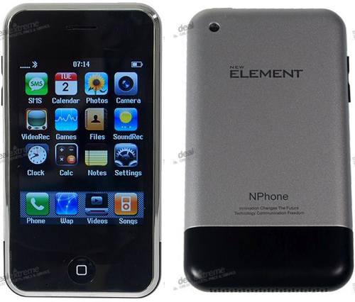
Nokia nPhoneIt is a great news for Nokia mobile users that Nokia will launch nPhone beside of iPhone.We've received exclusive news that Nokia have purchased iPhone brand today. Now it will be Nokia nPhone. In total for 1,5 billion dollars Nokia has got Apples iPhone TradeMark.

Almost all characteristics of phone will remain as announced: Multi-touch System, Intelligent Keyboard, Wireless, Built-in Advanced Sensors, but Nokia developers have made a decision to switch OS from
OS X to more Nokia native Symbian 9.1 OS. Sales of new nPhone are
expected on autumn of 2008 in US and in the beginning of 2009 in Europe and Asia."Be smart with new nPhone."

Holy cow - these fakes are getting pretty good. Look quickly and it’s tough to see that this is really labeled as an “NPhone”. It’s an overseas knock-off of the first generation iPhone. What I can’t figure out is that for the $200 they charge you could buy a genuine (and fully warranteed) 3G 8GB iPhone with software upgrade, ability to load App Store programs and best of all - guaranteed to work! I have no idea whether this will even sync to iTunes or hold a charge or cellular signal - but it might be fun to take into Apple’s Genius Bar and try to get them to service it.

Hacking Nokia cellular phone

Nokia cellular phone hacking

Many old Nokia cellular phones have graphical LCDs based on the PCD8544 controller. These are perfect for various electronic projects with microcontrollers. The interface is a two-wire serial type (clock and data), and some additional signals. The LCD supply is a single 3.3 V with very low supply current. This is not really a "hack"; we are merely re-using parts of the phone.

Note that information here is for the Nokia 6150 specifically. However many older models (e.g. Nokia 5110) are very similar, and hence most stuff is applicable also to those. Below is an image showing the different parts of the front PCB (back side has no components).

Note how the keypad is partly divided into rows and columns. This is because those keys are multiplexed in this way. The other keys are more or less randomly connected to the rows and columns. Each button has an edge area and a center are, between which a short-circuit is created when the button is pressed. The upper switch is used to turn the phone on and off, and the buzzer is what emits the loud beep when e.g. receiving an SMS. The three testpads are connected to the phone's internal circuits, and have no real use in this context.

Since the LCDs only have the conductive-rubber type of connection, the easiest method of hooking a microcontroller up to it is to re-use the whole PCB. The connection on the back has two rows of 14 pins each, which I numbered A1 through A14 and B1 through B14.

The image below shows the numbering convention I have used. Note that the ribbon cable was soldered to the board as part of the hack. It is normally not there when you open the phone.

A table below describes the function of each pin.

Pin Function Explanation
A1 LED & buzzer ground
A2 Switch output Shorted to A8 (ground) when switch is pressed
A3 LCD D/C Selects data (high) or command (low) for LCD communication
A4 LCD SCLK LCD serial clock
A5 LCD SDIN LCD serial data
A6 LCD /SCE LCD chip enable (active low)
A7 LCD /RES LCD reset (active low)
A8 Ground LCD ground supply, middle testpad, switch ground
A9 Buzzer control
A10 LCD Vdd Positive supply for LCD (2.8 - 3.3 V), LCD Osc (note 1)
A11 not connected
A12 LED control Set high to turn on LEDs
A13 Speaker 1 Differential driving through passive filter (?)
A14 Speaker 2 Differential driving through passive filter (?)
B1 LED & buzzer positive supply Ca +3.9 V supply (note 2)
B2 Connected to B3
B3 Connected to B2
B4 Leftmost testpad
B5 Row 4, "right" edge
B6 Row 3, "down" center, "hang up" center
B7 Row 2, "answer" center, "up" center
B8 Row 1, "left" center
B9 Rightmost testpad
B10 Column 3, switch output (through diode) (note 3)
B11 Column 2
B12 Column 1
B13 "Left" edge, "up" edge, "down" edge, "right" center
B14 "Answer" edge, "hang up" edge

Note 1: A decoupling capacitor is installed between LCD Vdd and LCD ground on the PCB.
Note 2: The LEDs are driven by a constant-current circuit, equal to (0.5*U(A12) - 0.7)/15 A for the display LEDs and (0.6*U(A12) - 0.7)/15 for the keypad LEDs. These formulas are valid as long as U(B1) is larger than 2.0 + 0.6*U(A12), which gives approx. 3.9 V as lower limit, but this is not critical. However, buzzer requires more than 3.3 V.
Note 3: The anode of the diode is connected to B10, and cathode to the switch output. Not sure why this wiring is used...

The LCD operates in the range 2.8 - 3.3 V, and hence all other signals should also be within that range. To use the LCD, required signals are: A3, A4, A5, A6, A7, A8, and A10. I will not go into details about how the signals are used, how stuff is written to the LCD, etc, since that is covered by the PCD8544 datasheet. However, I will give a proper initialization sequence, which is useful for checking that the LCD is working:

  • Reset LCD with a short low pulse on /RST signal at power-on
  • Command 0x21 (function set - extended)
  • Command 0xC6 (set operation voltage to 7 V)
  • Command 0x13
  • Command 0x20 (function set - basic)
  • Command 0x0C (configuration - normal mode)
  • Data 0xAA (turn on a few pixels)

The LCD should now show a vertical pattern of 10101010 in the top leftmost corner. You can download an ASM file for Atmel's microcontroller ATmega8. The file contains a program that writes some stuff to the LCD and then turns the contrast up & down repeatedly.

Once the basic communication is working, doing graphics on the LCD is not very difficult:


Nokia cellular phone hacking

Review Nokia E71

Review Nokia E71

Nokia E71: Smartphone with Smart Simplicity

The Nokia E71 is the successor of the popular Nokia E61 & E61i. Nokia had shrunken the E71 to just 57mm compare to E61i 70mm and trimmed it down to an amazingly 10mm thickness, an almost 4mm less thicker than E61i with 13.9mm

The display screen looks very sharp, which got narrower a bit at 2.36 inches (320×240 pixels) from 2.8″ with the E61. If there had to be a bit negative about Nokia E71, I say it’s going to be the keyboard, the QWERTY keyboard with the keys a little too crowded. However, it’s not bad at all since the keys more embossed so the user don’t easily hit neighboring keys. Another thing is that the number keys are at the center so you can easily type in single-handed. A fingernail-oriented user would feel more comfortable rather than thumb-oriented with the E71. The keys are enhanced by a nice back lighting which makes them very easy to read. The actual keys don’t actually light up but just the letters and symbols, which contribute to its clean and sexy exterior. Professional Design Trim and fitted with a full keyboard, Nokia E71 is impeccably tailored for business on the move.

The E71 features a business centric connectivity. The E71 includes A-GPS function, WiFi 802.11 b/g, Bluetooth 2.0 with A2DP, a microSD slot where you can add in an 8 GB of storage, a 110MB of built-in memory. Although the internal memory of 110MB is a little small considering the E51 has 130MB, but a dedicated 128MB RAM and ARM 11 369 MHz processor makes the phone woks express. There’s also plenty of software to take benefit for the quite-mature S60 platform. Really designed as a business device, the E71 comes with a full complement of office, email and PIM software, including a feature to switch on the fully between business and personal accounts, complete with separate mailboxes and home screens. It has two home screens that will allow you to choose between work and leisure modes. It enables you to choose application shortcuts to suit your schedule with message notifications on or off. The fast and easy access to messaging, including business and personal mail, without the complexity is a commendable feature of the Nokia E71.

However, one thing also that is not given much consideration with the NOKIA E71 is the 3.15 megapixel camera (2048×1536 pixels). The autofocus needs to be manually toggled each time you take the shot, a press on the “t” or “4″ key is necessary. Moreover, a dedicated camera button on the side is not available too, so one needs to use the middle button to take photos and videos. Video quality is limited to its maximum output at 15fps; nevertheless, a secondary front-facing camera for video calls is available.

Just as the E61 and E61i, the E71 houses a single speaker in the upper left of the phone. The audio quality is decent and sound volume is good. MPEG4 video playback is even and 3D tone is supported.

Choosing over many phones one will consider the battery life. With NOKIA E71, there should be no concern since it is fine. The BP-4L lithium polymer is rated at 1500 mAh. Nokia estimates a talk time of 10.5 hours. That’s pretty quite good. And turning off Wi-Fi scanning, one conserves more battery life.

Repair NOKIA 3510i / 3530 Circuit

Repair NOKIA 3510i / 3530 Circuit


Connecting a nokia 3510i / 3530 display to the parallel port:

The wiring is based on the wiring of optrex 323 and pcd8544-based displays to the parallel port. As i didn't know of any other projects like this (with nokia 3510i/3530 displays connected to the parallel port) i had to chose a wiring-'standard' for myself.

Wiring
Signals:
+------------------------+
1 2 3 4 5 6 7 8
# # # # # # # # 1 .. /RES
===#=#=#=#=#=#=#=#== 2 .. /CS
+--====================--+ 3 .. GND
4 .. SI (SDATA)
5 .. SCLK
rear view 6 .. Vio
connector is visible 7 .. Vflash
8 .. Vout
N3510i

+------------------------+

Signal name PC LCD Signal name
---------------------------------------------------------
Data 0 2 4 SI serial data input of LCD
Data 1 3 5 SCLK serial clock line of LCD
Data 2 4 2 /CS chip select
Data 5 7 1 /RES active low reset
Data 7 9 - Backlight (optional, not on display)
Ground 18 3 GND Ground for printer port and display voltages
-- 6 Vio 1.8V chip power
-- 7 Vflash 2.8V display power
-- 8 Vout output of display-internal dc/dc converter
(Vout -> capacitor -> GND to avoid noise)

circuits:


connecting n3510i/3530 displays to the parallel port


Part list: Part# Type Value Annotation

---------------------------------------------------------------------------------------
R1-R5 Resistor 1 kOhm
R6 Var.Resistor eg. 100 Ohm or higher value if needed;
or simply a resistor with fixed value
C1 Capacitor eg. 0.1 uF for stabilisation of display
(0.22 uF or other values are fine just as well)
T1 Transistor eg. BC547
D1 Diode eg. 1N4148

Remarks:
R5, R6, T1, D1 are needed in combination with LED background light only!be warned: without background light the display is hardly readable!
Vio ought to be connected to 1.8V but I did quite well without even connecting it.as always: just because it worked for me doesn't mean that it will work for you!
i used the original SMD-leds from the Nokia 3510i cellphone. they needed some value around 3.1V.as i didn't like to generate two voltages, i also connected Vflash to 3.1V (rather than connecting it to the recommended 2.8V)and one again: just because it worked for me doesn't mean that it will work for you!if your display dies in flames don't blame me.

Hardware reset vs. software reset:
to save one wire it is possible to replace the /RES-wire through a R/C-circuit.
part-list is the same as above with the following exceptions: Part# Type Value Annotation
---------------------------------------------------------------------------------------
R4 Resistor 10 kOhm
C2 Capacitor 10 uF

 
Mobile Phones Blog | Features,Concepts,Applications and Prices © 2012 | Designed by Cheap TVS, in collaboration with Vegan Breakfast, Royalty Free Images and Live Cricket Score