


Motorola V70 Dissection
Dissection is a Core 77 feature segment focused on understanding how the synergy of materials, manufacturing techniques, and design lead to innovative products. Its goal is to uncover the secrets of a design by conducting an autopsy on a coveted design object.
As designers and engineers, we spend much of our time justifying new processes, materials, and manufacturing techniques to our clients, when, in fact, many of us aren’t daily consumers of the products we create. We also rarely have the chance to review our products post mortem and witness how well they aged. However, if we can learn how products live, and in turn degrade, we can make better choices in our material selections, manufacturing processes, and their applications.
As is the case of any scientific dissection, the ability to learn about our specimen begins with the quality of the cadaver. The criteria for candidacy is that the object must be instantly recognizable, sought after, and utilize multiple and progressive manufacturing techniques. Today’s sacrifice to the design gods is my beloved Motorola V.70 twist phone.
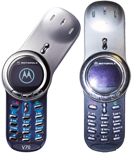 |
For those not familiar with our cadaver, it has a long history of design recognition. And, it has no doubt inspired myriad cases of gadget envy. The V.70 has been featured extensively in the design press including ID magazine and Innovation (Fall 2003) and it won a Gold IDEA award in 2003. It was brought to market in 2002 as part of Motorola’s resurgence in the mobile handset market where it broke new ground in both design, use of materials, and form. It was designed by Iulius Lucaci in Motorola’s Chicago office.
::Assessment of exterior treatments, materials, and techniques:: The designers of the V.70 strove to create a phone with a tough exterior shell, like an exoskeleton, complimented by a more comfortable, soft, and tactile inside. The exterior metal of this phone is particularly interesting as it involves multiple production processes to achieve its final look and feel.
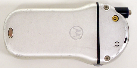
This phone was a showcase product for Motorola, and as such, they did not spare any expense in producing a very unique device. The exterior aluminum shell serves not only as a structural element, but also as a design feature. It is also the most interesting of the phone’s components. The battery cover housing of this phone begins as 0.70mm aluminum (fig.01). The housings are first stamped to get their overall shape. Secondary operations include the stamping of holes for the battery release door, fasteners, and selection button. Tertiary operations include the folding of retaining guide rails. And finally, the company brand on the back of the outer housing is stamped, then completed by a mill pattern.
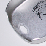
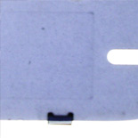
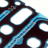
Internally, removal instructions are pad-printed on surface of the aluminum (fig.02).
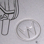
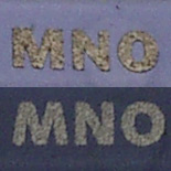
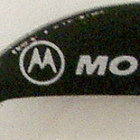
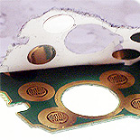
The final process of milling the back brand mark is perhaps the most unique, and expensive (fig.03). Although it is difficult to tell from the production parts, it would appear the entire process is a secondary stamp, then a machine treatment; this feature thus appears as a hand crafted detail, truly adding to the jewel-like quality of the phone. The expense of this operation comes from its precision. The stamp of the mark is 0.2mm deep, while the final machined mark is a mere 0.07mm in height.
The top antenna cover is created in a similar manner; however its material begins as 0.50mm aluminum. This indicates that the top and bottom housing were created independently of each other with two separate tools. Additionally, the variation in thickness may be to allow better radio reception in the top housing, or may be within the manufacturing tolerances of the part. The antenna housing also has a small rubber/elastomeric stopper which covers part of the antenna assembly. Again, this is most likely to aid transmission signals, or provide access to the phone. The stopper appears to be a medium durometer elastomer. The antenna housing is fastened to the body by two Torx fasteners on either side. This adds yet another unique and jewel-like touch to the design.
Both of the housings appear to be satin finished via a media blast or brush technique. The texture is very light and no doubt applied to mimic the silver paint of the top surface. The surface then appears to have a very light clear coat. However, it is not anodized, and as a result, scratches easily.
The choice of aluminum has impacted the longevity and durability of the part. Where other painted elements of the phone show wear, the aluminum remains intact. Although this phone has been dropped numerous times, the only blemishes to the metal are a few scrapes and scratches. In short, far better resilience then a painted surface would have seen over time.
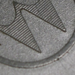
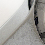
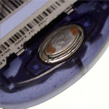
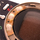
As we move to the top side of the assembled phone we see a great mixture of manufacturing techniques. The top half of the phone is painted silver. The rotor housing shows a very apparent difference between the OEM and AM parts (fig.04) The Motorola parts lasted for a little over the year and had little signs of wear. The AM parts however, took merely a couple of months to wear completely to the plastic. This can likely be attributed to the quality of the paint used and the preparation of the plastic.
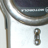
The top housing has allotment for a small speaker port at its top as well as a navigation switch near its bottom. The navigation switch is a rather ingenious pass through to the internal key pad when closed (fig.05) This allows for operation of the phone when closed, but doesn’t require running additional electronics to the switches. The speaker has two faux openings and one real speaker port. There is a thin mesh behind each of the faux ports which prevents you from seeing all the way through the housing.
While the front of the rotor unit is composed of standard ABS or PC/ABS, the back snap fit piece is coated with a soft-touch spray. Given the thinness of the coating, it appears to be sprayed, vesus overmolded or doubleshot. This finish really adds to the tactility of the phone and makes it feel more human than a plastic or even metal part.
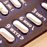
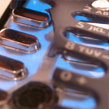
The soft-touch treatment is repeated on the number pad, another ‘high-touch’ area (fig.06). This is one of the great surprises of using this phone, as it is something you wouldn't expect on first encounter. The number pad is also pad-printed with numbers, letters, and answer/hang up icons.
Both of the soft touch pieces are made of translucent plastic. The plastic is, again, most likely an ABS or PC/ABS blend. The plastic on both sets of parts exhibits a good amount of flex; therefore its mixture is heavily weighted toward ABS. Another significant reason for its flexibility is for the large amount of snap-fits that connect the phone's housings together. While the phone’s tolerances are high, the slightly more flexible resin allows for easier assembly and therefore fewer defective parts.
The rotor is adorned with a chrome bezel that encircles the phone’s screen. The bezel begins as an injection molded plastic part, which is then plated. The bezel is completed by the addition of the navigation button assembly. These buttons, though they appear trivial, are actually a rather complex part as we will see when we disassemble the bezel.
The screen is protected by a piece of Lexan or similiar Polycarbonate resin. This piece is created using IML/IMD. IML/IMD, commonly referred to as In-Mold Labeling/Decorating, is a maturing new technique which allows for the integration of a graphic film into a plastic part. This is a great example of when and why to use this technique. Not only does IML provide a window to the screen, it protects the screen, and provides a space for both product branding and screen matte. The use of IML also ensures the longevity of the screen as PC is very resilient to wear.
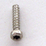
::Disassembly of mechanical fasteners and user removable components:: The exterior disassembly begins by removing the back battery cover. This is accomplished by depressing the battery switch and forcing the cover over the switch. The next step is to remove the two Torx .75 metric thread 8mm fasteners (fig.07).
Doing so uncovers the underlying plastic skeleton. Though the outside of the phone relies on protection from the aluminum housings, by and large, the real structure of the phone is provided by plastic. The internal plastic is a transparent resin, which appears to be identical to the other ABS/PC ABS material used on the touch surfaces of the phone. Its wall thickness varies from feature to feature of 0.75mm to 1.1mm. The internal structure is slightly textured (Mold tech: MT1005-1), though is still fairly unrefined as it is the b-surface of the part and would rarely, if ever, be seen by a user.
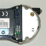
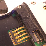
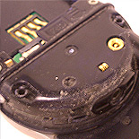
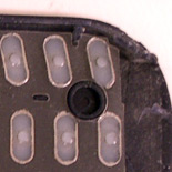
The removal of the covers reveals the GSM SIM card, battery contacts, two additional metal contacts, and part of the antenna assembly (fig.08). I was unable to draw a conclusion as to the function of the two metal contacts. My first assumption was that they informed the phone if the covers were not present (fig.09). Having removed the covers, and was still able to operate the phone, I rendered that hypothesis false. Further, as the phone did operate without the covers, my second hypothesis about the contacts being a ground, or completing a circuit, was also rendered moot.
The bottom battery housing is connected to the top keypad housing by 6 snap fits. These two housings encase the internal electronics.
I continue the first level interior dissection by turning the phone over and removing the front bezel. The front bezel is a removable "style" accessory; users can choose from three different options that ship with the phone (gold, silver, and black). However, there are other AM options available. The bezel is removed by pressing down and turning counterclockwise. Once the bezel is removed, we are left with the aforementioned IML LCD cover, three dome switches, and the metal rotor housing.
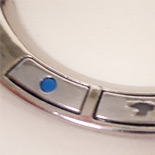
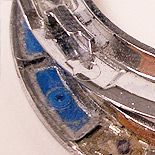
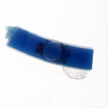
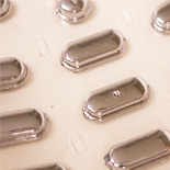
The bezel is home to three buttons. The construction of these buttons is truly interesting, and frankly, a bit bewildering. The assembly consists of three parts. First, the blue buttons are injection molded (fig.12). They have a circular boss that protrudes through the second injection molded and plated part (fig.10,11). Finally, that assembly is adhered to a thin acetate-like substrate (fig.11). The dome switches beneath don’t require anything but pressure to make contact, so it would seem that this process has largely been utilized for aesthetic reasons. The buttons are then captured by pressure between the ring and phone substructure. You will see a similar technique used for the number pad keys, though implemented slightly differently.
::Disassembly of electronic components and non user serviceable components::
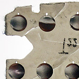
To begin the second level of dissection, I remove the second set of Torx screws (fig.13). I then unfasten the 6 snap fits that attach the battery housing plastic. This releases the back housing—and everything else inside it. With the back housing free, the electronic package is allowed to move freely, and disengage as one piece. The phone now exists in three pieces: the back housing, the electronics package, and the rotor assembly and keypad.
The upper rotor assembly now consists of IML lens cover, neoprene gasket, dome switches, keypad keys, top plastic keypad housing, silver rotor housing, and its back cover (fig.14). All of which are joined to the metal substructure.
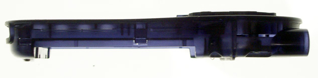
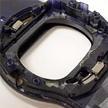
The back housing, now devoid of much interest, remains home to two metal contacts, an elastomer selection button, and the battery cover release button assembly (fig.15).
The IML window settles itself within the metal substructure and removes easily as it’s a press fit part (fig.16). The gasket is lightly adhered, and pulls off easily, while the chrome key pad is simply captured by pressure between the circuit board and the top plastic housing. The dome switches on the bezel must be ‘fished’ through the housing to be removed (fig.16,19).
The chrome key pad uses a similar technique to the navigation buttons of the chrome bezel (fig.18). However, the implementation of this key pad is slightly different. While the bezel buttons were adhered to the film substrate, the chrome buttons appear to be either heat staked or ultrasonically welded. I would guess that they are heat staked to the film substrate, as I have successfully managed to pry one or two off of the film. While the bezel buttons are two individual pieces, these are only one.
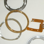
To disassemble the remainder of the upper rotor assembly requires some manual effort, a bit of dexterity, and some luck as to not crack any of the plastics. The metal sub structure captures the silver top housing by grabbing onto the bottom housing via two metal L-bracket tabs (fig.21). To release the two parts, the metal substructure must be disengaged from the bottom plastic. Once free, we can see how the phone communicates its rotor state electronically (fig.20).
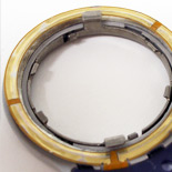
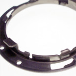
Removing the top housing reveals the metal contact strip which communicates whether the rotor is open or closed. It does this in a relatively simple and elegant way. In the phone’s case, this metal conduit has two very important jobs. It must first determine open vs. closed, and secondly it must transfer sound to the speaker. To determine state, the metal ring is broken up into three sections, with dead spots separating the active areas. When the phone is closed, its sensors read a dead area, and when open, vice versa, hence telling what configuration it’s in (fig.22). It’s a very simple solution to what seems to be a complex interaction. While communicating digital voice data is a bandwidth constrained process, analog sound reproduction is simple, and the phone’s connection points provides ample signal strength to drive the speaker.
To completely disassemble the upper housing, the back plastic cover has to be removed. This is accomplished by unseating the snap fits which hold it together. The back cover is a very well made part. Its tolerances render it extremely difficult to remove, and by doing so, allow it to capture the speaker assembly in place without adhesives (fig.23). The back cover is also textured on the underside (MT11010). This helps add to the depth of the soft touch finish, reduce the light transfer, and hide the lifter/slider lines. In fact, from a manufacturing standpoint, the lifter lines are barely noticeable. This is an excellent example of the ability for texture to hide sink marks, lifter lines, slides, and flow inconsistencies (fig.24).
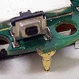
This disassembly reveals the internal speaker assembly as well as the toggle switch assembly (fig.22). The toggle assembly consists of a plated plastic part and an elastomeric sleeve. The sleeve serves to help seat the part, as well as ensure that the user’s pushes get translated to the underlying keypad. The elastomer also aids in dampening the switch’s action.
::Disassembly of electronics package:: The final focus of this dissection is the phone’s electronics package. One of the biggest selling points of this phone was its size, and the sheer amount of electronics that Motorola has integrated into the package is quite amazing. While I’m not qualified to deconstruct everything from an electrical engineering stand point, designers should take note of how Motorola was able to reduce not only component height, but also connector height. In doing so, they made the electronics portion an easy assembly for factory technicians/machines.
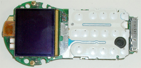
The electronics package consists of an electroluminescent keypad, the main board, the LCD, and the SIM card reader—all of which use low profile, pressure-fit connectors. At its highest point, the entire assembly is a mere 12.0mm. There are four very intriguing elements to the electronics package which were either unique to this phone, or were revolutionary at the time.
The first, and perhaps the most “whiz-bang,” is the integration of electroluminescent lighting, or EL for short. While EL has been around for quite sometime, Motorola was one of the early adopters. This application showcases the true usefulness and practical application of EL (figs.25 ,26, 27). Motorola has also gone a step farther and integrated the EL directly into a very unique dome switch keyboard.
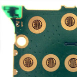
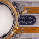
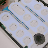
What we can see by peeling back the EL layer is a very unique approach to using dome switches (fig.28). Motorola took a different approach in assembling this key pad. Instead of assembling an array of dome switches where individual components communicated via cable to the board (like the bezel dome switches), they cut out the middle man. The domes are adhered in their array directly to the board (fig.29). The EL layer is then adhered to the film and electrically connected to the board. The keyboard contacts are built into a single PC board. This implementation dramatically reduces the amount of electrical traces, component height, and cable routing associated with the keyboard design (fig.30). Although small, it allows for better tactility than an elastomer solution would have provided, not to mention a substantial height savings. The keyboard connects to the mainboard via a simple pressure fit connector (fig.31).
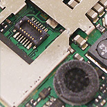
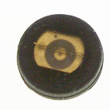
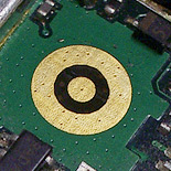
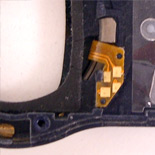
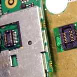
The top of the package is also home to both the microphone and communication connectors between the phone and bezel (fig.31,32). The microphone implementation reveals an interesting solution to the problem of connecting a microphone to its required 2 leads. Instead of using two wires, or concurrent chases, the implementation here calls for two concentric contact rings. These rings allow the microphone to sit freely on the main board with no worries regarding adhesion or loose solder joints (fig.33). This implementation requires far less space and ensures that the microphone can actually spin 360 degrees without loosing contact; thereby making both component assembly and the phone more reliable. The bezel contacts which transmit sound to the bezel are interesting as they are simply spring-loaded posts which protrude on either side of the LCD (fig.35).
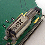
Finally, the main board is home to an oscillating motor—the same type you’d find in your home hand sander, only much smaller (fig.36). Motorola was one of the first companies to include vibration as an alterative call notification technique. Prior to on board motors, manufacturers were accustomed to incorporating oscillating motors into their battery packs.
It is clear that the level of both manufacturing and electronic complexity which went into this V.70 is immense. This phone’s complexity from a materials and production point of view is amazing. However, it is equally impressive when considering its technical and assembly hurdles. This phone served Motorola well as a showcase for design ingenuity and their ability to package complex electronics.
It is certain that the manufacturing decisions behind this phone greatly impacted its appeal and captured consumers’ attention. However, the choice of these production techniques greatly impacts the phone’s longevity, not merely aesthetics. This phone illustrates also that beyond the technique used, the vendor providing those services is critical in producing both an aesthetic and lasting product.
Our job as designers is not only to design aesthetically, but also for the elegant degradation of our products. The V.70 illustrates this point perfectly. While not inexpensive to produce, the cost is justified through both its longevity and looks.
As you encounter your next design problem, think about how material selection, spray coatings, electronics packaging and manufacturing techniques can help develop a unique and compelling experience for your product. Remember it is not merely aesthetics that sells products, but longevity and user experience which gains trust, builds brands, and ulitmately creates loyal, repeat consumers.


0 comments:
Post a Comment